Truss
propertiesTruss
properties
Truss
propertiesTruss
propertiesMany of the truss parameters can be edited from the Object Info palette; other truss parameters can be edited from the Truss Properties dialog box; see Setting custom truss parameters.
![]()
![]() Click
to show/hide the parameters.
Click
to show/hide the parameters.
Parameter |
Description |
Orientation parameters |
To orient the truss, Vectorworks applies the Roll, Hanging Angle, and Rotation settings in this order |
Roll |
Rotates the truss object on its X axis; the truss rotates around its insertion point |
Hanging Angle |
Rotates the truss object on its Y axis; the truss rotates around its insertion point |
Rotation |
Rotates the truss object on its Z axis; the truss rotates around its insertion point |
Properties |
|
Symbol |
Displays the truss symbol |
Type |
Displays the truss type, manufacturer, or catalog identification number |
Name |
Identifies the truss section; if the truss is converted to a hanging position, the name of the hanging position displays automatically |
ID |
Unique identifier for truss calculations and labels; if blank, a value is automatically assigned when calculations are run (Braceworks required) |
Height/Width |
Displays the height and width values of the truss |
Total Weight |
Sets the total gross weight of the truss; corner trusses are considered as point loads in calculations, while all other truss types are considered as distributed loads |
Distributed Weight |
Displays the weight per unit of length for the truss |
Length (straight or curved truss only) |
Displays the length of the truss |
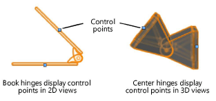
Hinge Angle (hinge truss only) |
Sets the angle between the hinge parts. You can manually adjust the hinge angle by moving the control points on the hinge truss.
|
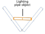
Insert Locking Pipe (book hinge only) |
Inserts a lighting pipe to connect and lock the hinge parts. The lighting pipe is considered as a separate object in Braceworks calculations.
|
Cross Section |
Displays the cross section unique ID number, when a cross section file has been associated with the truss as described in Specifying cross section data Cross section information is required for valid calculations; if there is no identified cross section, calculations will not be complete. |
Connectable with |
Displays the ID of rigging objects that can be connected to this truss in Auto Connect mode, forming a structural system |
Truss System |
Displays the name of the truss system to which the truss belongs, along with the truss line number |
Display |
|
Draw 3D Only |
Hides the 2D-only portion of the object, making it easier to view and rotate in 3D views |
Center line |
In Top/Plan view, displays the truss center line; some load objects are attached at the truss center line |
Actions |
See Modifying trusses and systems for parameter descriptions |
|
Click here for a video tip about this topic (internet access required). |
~~~~~~~~~~~~~~~~~~~~~~~~~
Creating a custom truss symbol
Setting custom truss parameters
Changing the trim height of a system
Concept: Creating a connected rigging system