 Creating the rigging systemCreating the rigging system
|
Tool |
Tool set |
|
Truss
|
Rigging |
The Truss tool places a section of truss on the drawing. Depending on the resource selected, the truss may be a straight, curved (or circular), hinge, or corner element.
You can place one truss at a time, or place multiple straight trusses, to create a truss line. Trusses can be inserted horizontally, vertically, or at a custom hanging angle. In Auto Connect mode, the trusses connect to existing trusses, forming a system. When Auto Connect is disabled, the trusses do not connect to existing systems.
Use the Data Tag tool to add a label to the truss; see Gegevenslabels gebruiken.
|
Mode |
Description |
|
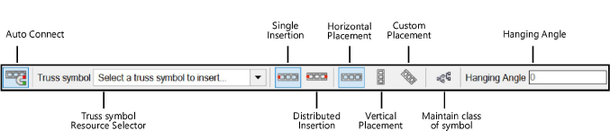
Auto Connect |
When enabled, connects the inserted truss to the current truss system with geometrical precision; also generates a preview of connected trusses that are being moved |
|
Truss symbol |
Select the truss to insert |
|
Single Insertion |
Inserts a single truss object on the guideline |
|
Distributed Insertion (straight truss only) |
Inserts multiple truss objects along the full length of the guideline |
|
Horizontal Placement |
Places horizontal trusses; the hanging angle is 0 (zero) degrees |
|
Vertical Placement |
Places vertical trusses; the hanging angle is 90 degrees |
|
Custom Placement |
Places trusses at the specified Hanging Angle |
|
Maintain class of symbol |
Uses the class specification from the symbol definition; disable the mode to insert the truss into the active class instead |
|
Hanging Angle |
Specify the hanging angle for Custom Placement |
A truss object whose symbol definition cannot be located will display with default geometry, until a replacement symbol is assigned.
~~~~~~~~~~~~~~~~~~~~~~~~~
