 Concept: Schematic views
 Concept: Schematic views
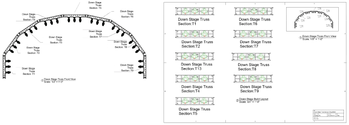
The Create Schematic View command uses the 3D model to create easy-to-read 2D views for paperwork. Specify the 2D view for each schematic view while preserving the 3D model’s orientation and view settings. For example, print schematic shop drawings in Top view while maintaining a Front view of the model for section viewports.
To reduce file size, schematic views do not duplicate model objects. Instead, they provide a live 2D reference of the 3D model geometry.
Schematic views are interactive; you can move, rotate, and mirror schematic rigging and load objects. Much like the 3D model, when a schematic rigging object is repositioned, the attached schematic loads move and rotate with it; see Concept: Attaching loads to rigging objects. Because schematic views are 2D only, they do not participate in Braceworks calculations.
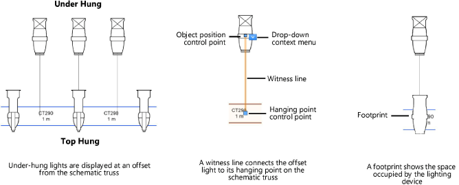
Schematic views can show equipment that is obstructed from view in the model. For example, offset under-hung devices to make them visible in a schematic Top view. Witness lines indicate the devices’ hanging points on the truss. Hanging points define where the associated loads are calculated in the 3D model (Braceworks required). Optionally, a footprint on the schematic rigging object indicates the space occupied by the load.
To control the attributes and visibility of witness lines and footprints, set their classes on the Spotlight preferences: Loads and Rigging pane.
The color settings on the Spotlight preferences: Lighting Devices: Classes and Color pane also apply to lighting devices in schematic views.

The model and its schematic instances are linked in a parent-child relationship. They interact in the following ways:
|
Action in model |
Result in schematic view |
|
Move a load's hanging point on the associated rigging object |
Moves the corresponding load on its rigging object. If the corresponding load is offset, only its hanging point moves on the rigging object. The load’s offset position does not change, but its witness line updates to stay connected with the new hanging point. See Moving schematic loads by control points . |
|
Rotate a load |
None |
|
Move or rotate a rigging object |
None |
|
Attach a load to a rigging object |
Adds a load to the corresponding rigging object in the same relative position as the model load |
|
Attach an accessory to a lighting device |
Adds an accessory to the corresponding lighting device |
|
Remove or delete a load |
Deletes the corresponding load |
|
Delete a rigging object |
Deletes the corresponding rigging object and any attached loads |
|
Number light plot objects |
Numbers the corresponding objects |
|
Update a lighting device’s 2D label legend |
Updates the 2D label legend of the corresponding lighting device |
When the 3D model is edited, schematic views may not update automatically to reflect the changes; see Updating schematic views for more information.
|
Action in schematic view |
Result in model |
|
Move a load's hanging point on the associated rigging object |
Moves the corresponding load on its rigging object |
|
Move a load to an offset position |
None |
|
Rotate a load |
None |
|
Move or rotate a rigging object |
None |
|
Attach a load to a rigging object |
Adds a load to the corresponding rigging object in the same relative position as the schematic load |
|
Attach an accessory to a lighting device |
Adds an accessory to the corresponding lighting device |
|
Remove or delete a load |
None |
|
Delete a rigging object |
None |
|
Number light plot objects |
Numbers the corresponding objects; for automatic numbering, the order is determined by the location of the schematic objects |
A schematic lighting device shows the 2D label legend of its parent device.
When Numbering light plot objects, the model objects and their schematic instances are considered to be identical. For automatic numbering, the location of the schematic objects determines the numbering order.
|
|
Click here for a video tip about this topic (internet access required). |
~~~~~~~~~~~~~~~~~~~~~~~~~